|
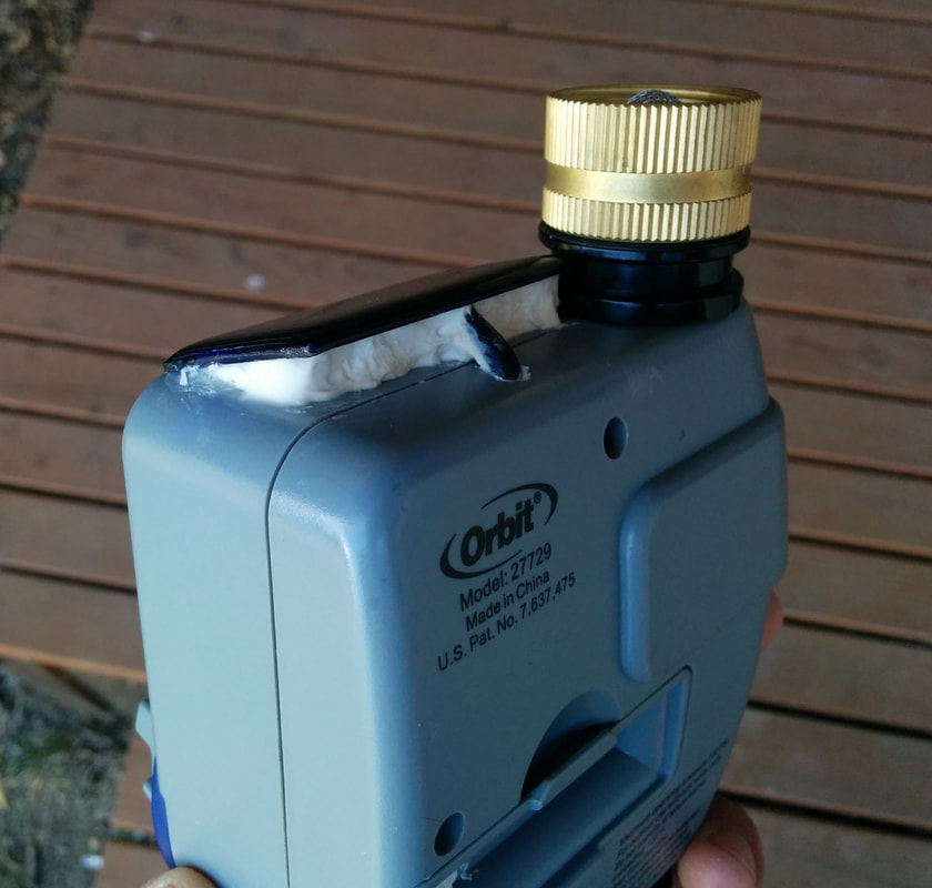
Update 5/9: Added a part selection explanation to the end of the blog post. I found an old Orbit 27729 Digital Hose Timer that I wanted to use to water newly planted trees.  Rather than dealing with replacing/wasting batteries every growing season, I decided to use $15 in parts to convert the hose timer to solar.
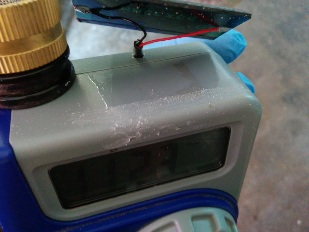
 Finished shots first. Everything is concealed within the timer enclosure and the solar panel on top. With a bench power supply I was able to test basic functionality and measure current draw of the device, which is less than 1mA in idle and about 200mA for less than a second when the valve kicks. 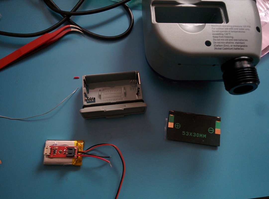 The idea was to mount the battery and battery charger in the water resistant battery tray and connect to the existing battery tray terminals. This way I can just plug the tray in to power the device (same operation with AA batteries). The cable from the solar panel was run through the enclosure and connected to the battery charger internally, rather than having an external wire. 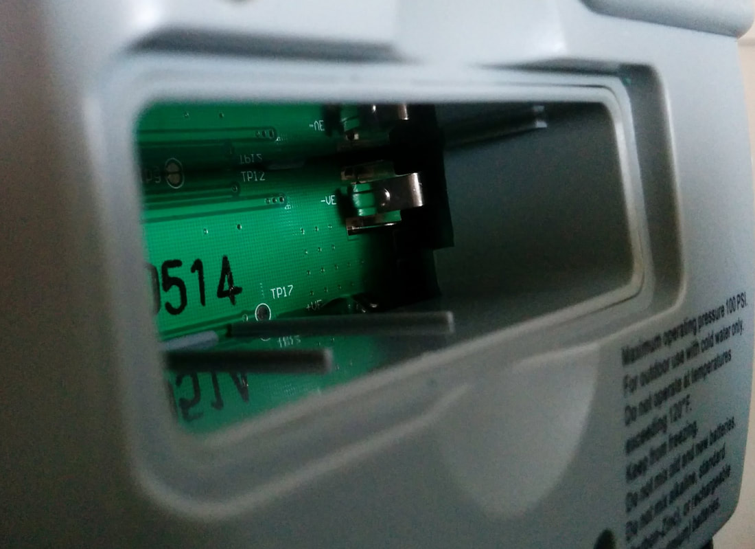 Identifying the positive and negative terminals was easy. Note the -VE and +VE silkscreen indicators on the PCB. 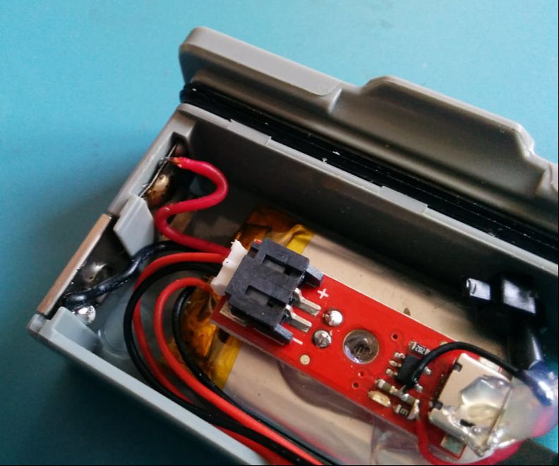 Using double sided tape, mainly for support soldering, I mounted the battery to the battery tray and the battery charger PCB to the battery. A micro-USB type B wouldn't fit in there, so I had to find the VCC and GND traces/pads on the PCB and solder wires to them. I used a little hot glue for strain relief. One problem I ran into was that soldering to the battery terminals was difficult. I decided wire wrapping the terminals will work better. The black wire on the bottom left (image above) is wrapped around one loop of the spring connector and the red wire on the upper left is wrapped through an existing hole. 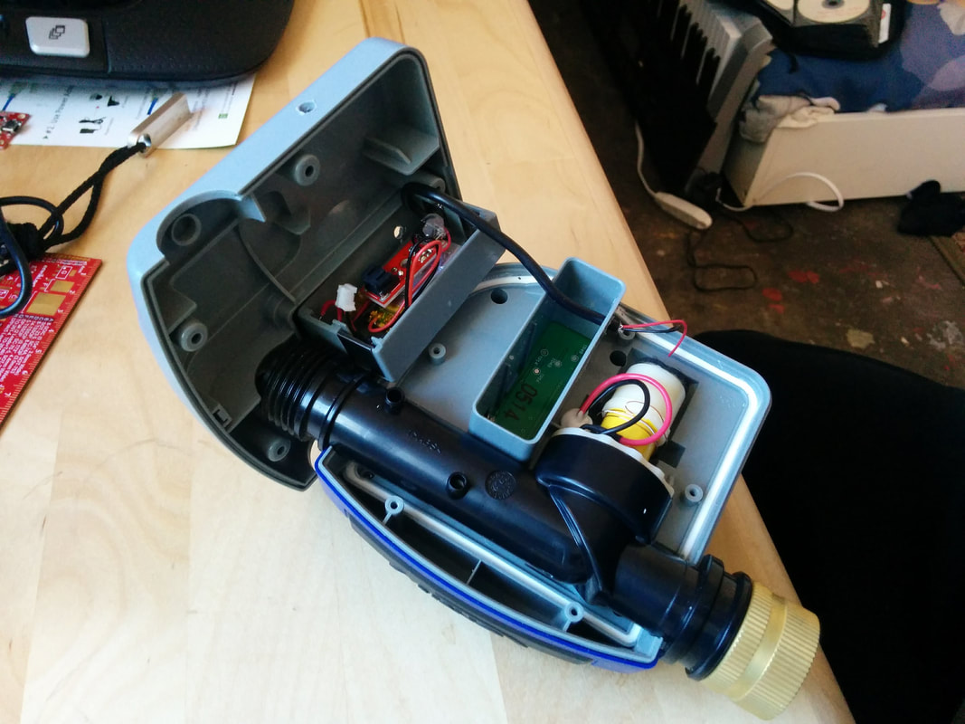 Opening the timer revealed lots of room. I Dremeled two holes and ran the wire to the solar panel. I forgot to remove the charge LED for the battery charger, so I did that in this step, then plugged the battery in and closed everything up. 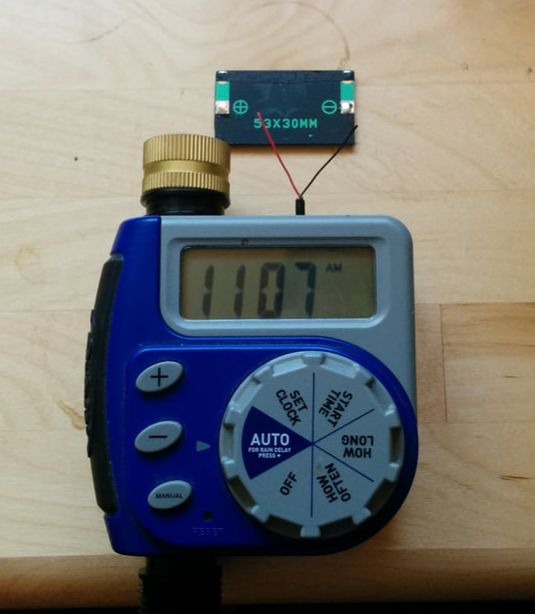 I soldered the wires to the panel and sprayed an acrylic conformal coating over the terminals to protect against moisture/air ingress.
The solar panel was super glued to the plastic (after scoring) and I filled the gaps behind the panel with white liquid nails construction adhesive, not ideal, but it was all that I had lying around ATM. 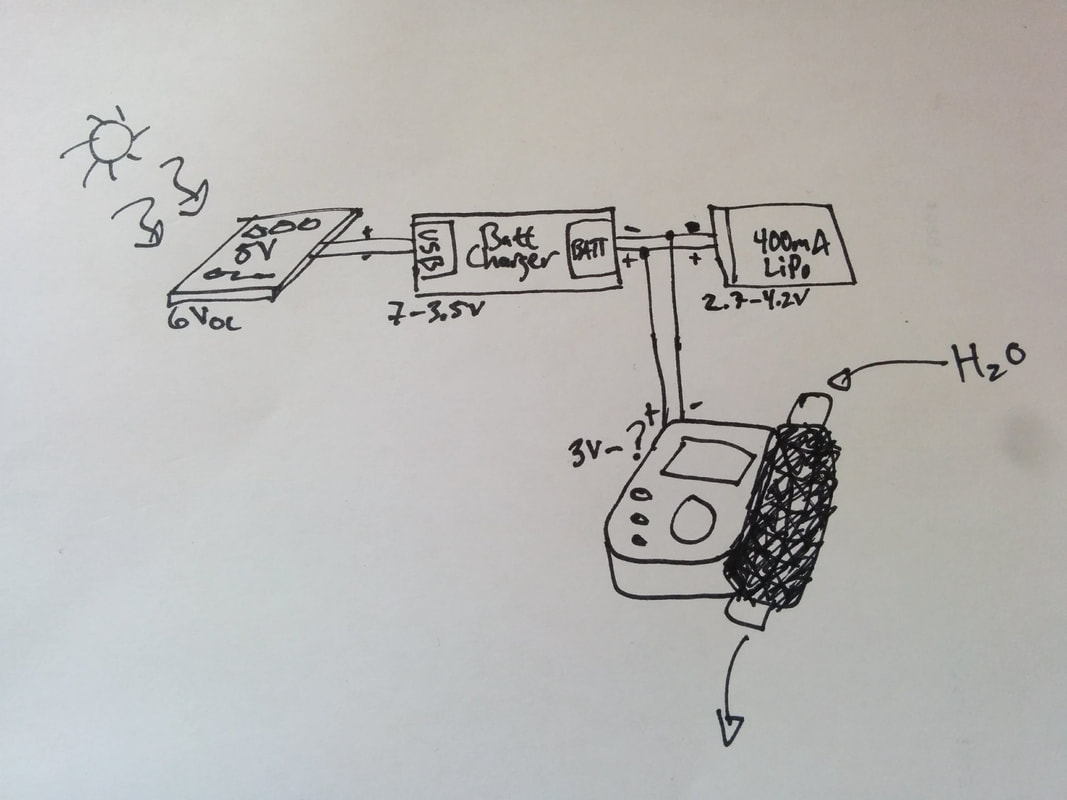 Here is a napkin schematic of the simple circuit. Why does this work? Read below for part selection details. Solar Panel Selection
I want to make sure my small 0.15W solar panel will deliver more than enough power for the timer. To do this, compare the power generation of the solar panel with the power consumption of the timer. Here are the values, usually from datasheets or measurements taken:
When looking at the total power budget, it is much easier to work in units of energy rather than instantaneous values like current and power. For example, the time it takes to turn the valve on or off or how long the solar panel provides power in the sun is included in the energy calculations. Simply determine the period constant where everything repeats, which for this project is 24 hours, i.e. I want to water once a day. Now, convert the instantaneous values of current and power, into continuous values of energy in watt*hours over 24 hours. For the solar panel:
For the timer:
To summarize, on average, in a 24 hour period, the solar panel will generate 0.72W*h and the timer will draw 0.11W*h. Solar is generating roughly 7 times more energy per day than what the timer is consuming. Good deal, this tiny solar panel should work! We aren't out of the woods yet. Battery capacity selection is important as well! Battery Selection The average power draw for the timer is very low, the timer draws only draws 26mA*h in 24 hours. Why not just use a 30mA*h or 50mA*h battery if the solar panel will charge those back with 7x more energy? When the valve turns on, our battery needs to provide at least 200mA of current very quickly. I'm using a single cell LiPo battery, which has a 1C discharge specification. This means, at most, the battery can only deliver it's rated capacity. For example, a 200mA*h battery will only deliver 200mA at most. Note: This is why on the hose timer battery cover, it says only to use alkaline batteries, because NiMH and Li-ion AA batteries have much lower C ratings than alkaline and might not be able to deliver the 200mA punch for the valve, especially when running low on capacity. In addition, the 200mA draw for the valve was just an average I read on my power supply and the actual spike is likely somewhat higher. Given all of this, I choose to over rate the battery as much as possible, while making sure it still fits in the battery tray. I choose a 400mA*h battery. System Supply Over Voltage One final potential issue that was not resolved: The LiPo battery is fed directly into the timer, replacing 2 AA alkaline batteries, which are nominally 3V. The single cell LiPo battery I used could go as high as ~4.2V. Before starting the project, I ran the setup on a bench top power supply for a few days with no issues. I could have included a buck/boost supply regulating the timer to 3V, but that ads cost and power consumption and this is supposed to be a fast and inexpensive hack. My assumption is that there is a downstream voltage regulator internally within the timer for the digital bits anyway.
8 Comments
|
 RSS Feed
bitsmashed limited © 2023